Cathode Ray Oscilloscope - CRO
Welcome to the Interactive Cathode Ray Oscilloscope (CRO) Tutorial!
Ever wondered how scientists and engineers see electricity? Buckle up, because this interactive tutorial will turn you into a CRO wiz! Forget dry lectures – here, you'll get hands-on experience with a virtual CRO simulator.
Ready to unlock the secrets of waveforms?
As you explore the different controls, you'll see the effects in real-time on the oscilloscope screen. We'll break down the CRO's components, teach you how to interpret those squiggly lines, and even show you how to measure voltage and frequency.
By the end of this tutorial, you'll be able to:
- Identify the key parts of a CRO
- The uses of the Cathode Ray Oscilloscope - CRO
- How the CRO works
- Thermionic Emission
- Voltage gain or Y-gain
- How the time-base and voltage multiplier work
- How to calculate the frequencies and voltage of an AC
- A simulator to practise the calculations - fully interactive
The Cathode Ray Oscilloscope, CRO, is a very useful instrument in the field of electronics. It can be used to measure:
- Voltages - AC or DC
- Frequencies
- Small time intervals
- Phase Differences or to draw Lissajous figures.
This tutorial is primarily for those who learn physics at A Level and IB. There is a fully interactive applet for you to practise and learn at the end of this tutorial. You can
change the voltages and frequencies while practising in order to see how they affect the shape and size of the AC.
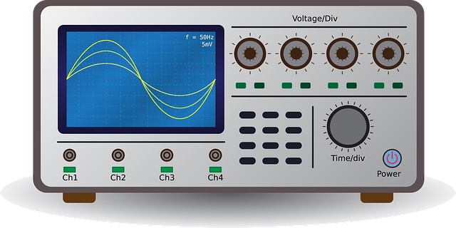
The CRO, cathode ray oscilloscope consists of an electron gun, a pair of vertical and horizontal plates which could be provided with voltages so that the beam of electron could be diverted on a fluorescent screen.
Thermionic Emission
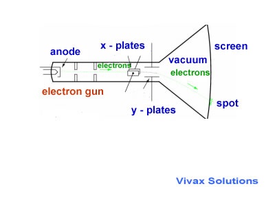
The electron gun consists of a coil mounted behind an anode. The coil is heated by a battery so that it can emit electrons continuously, which in turn, are attracted to the anode, mounted next to the coil. This process is called thermionic emission.
The presence of the anode accelerates electrons towards it and then beyond it through a hold at the centre of the anode, which becomes the electron beam of the oscilloscope. When the oscilloscope is switched on, the beam creates a spot on the fluorescent screen.
The animation shows how the beam of electrons is produced and then diverted up or down or sideways by applying voltages to y-plates and x-plates.

Y-gain/Voltage gain and Time base
When a voltage is applied to y-plates, it can be seen on the screen with a corresponding line. Using the voltage/gain knob that shows V/div we can determine how it should be displayed on the screen.
On the other hand, when the time base is switched on, an internally generated AC sweeps across the screen at a constant speed, from the left to the right of the screen, and then back to the left at a very high speed, which is barely noticeable. The speed - from the left to right - can be changed by the knob of the time-base control. If an AC is connected to the Y-plates when the time-base is on, the fluctuation of voltage against time becomes visible on the screen.
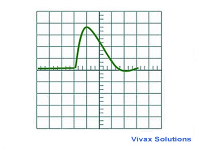
Measuring the voltage and frequency of an AC
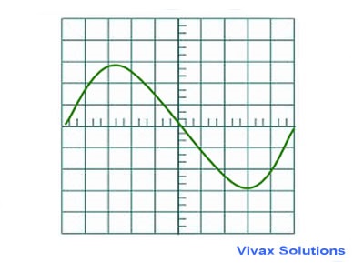
Suppose 1cm on vertical scale represents 80V and 1cm on the time-base represents 2ms.
The maximum height of the AC = 3cm
So, the peak voltage = 3x80 = 240V.
Vrms = 240 / √2 = 169.7V.
The length of the cycle = 10cm
So, the time period of AC = 10x2=20ms
Frequency of the AC = 1/T = 1/20x10-3 = 50Hz.
Measuring the DC current
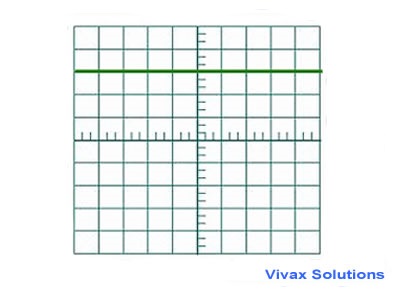
A DC gives generates a horizontal line, above or below 0, depending on the nature of the voltage.
in the above example, if 1cm on the vertical scale represents 3V,
The voltage of the DC = 9V.
Measuring a small time interval
To measure a small time interval, say that of an ultrasound pulse, the time-base must be connected to the pulse generator and the receptor to the y-plates. Suppose the distance between the two is d.
The departure of the pulse from the generator and reception by the receiver are recorded on the screen as follows:
If 1cm on the horizontal scale represents 2ms,
Time taken by the pulse to travel a distance d = 2x4 = 8ms
So, the speed of the ultrasound pulse = d/2x10-3 = 500d ms-1.
Advantages of a CRO
- Resistance is very high - that means it draws very little current.
- It can be used to measure both AC and DC voltages.
- Since there is no coil inside it, the issue of burning does not arise.
- The response is instantaneous, regardless of the size of the voltage.
- Intensity and the focus of the beam can easily be adjusted.
Cathode Ray Oscilloscope - simulator
You can practise the cathode ray oscilloscope here: change the time base of the wave and find the frequency; find the maximum voltage of an AC voltage; and many more can be performed.
E.g.
If you choose the time base as 5ms/Div,the time period, T, of the AC is 6 divisions is, 5 X 6 = 30ms.
frequency = 1/T
= 1/(30/1000)
= 33Hz
Now that you have read this tutorial, you will find the following tutorials very helpful too: