Logic Gates
Diodes
A device that can control the direction of the flow
of a current is a diode; it is made of semiconductor materials such as silicon.
As you can see, the position of the diode can turn the current on
or off.
That means, a diode can be used as a one way switch: if the wider end of
it faces a positive terminal of a battery, it lets current through or else it
cuts the current off.
Based on this system, a couple of switches are made
and they are called logic gates.
The input of these gates can be combinations of 'On' or 'Off'
states and they are known as '1's or '0's. These are binary digits, that has been the
basis of the Binary System. The output can also be
'0's or '1's. That means, we can
express the output of these systems in terms of
'1' and '0' - binary digits.
In
other words, the output of the logic gates can be used to interpret the numbers
in binary form. This is the birth of computer systems; they recognize only '0' s and '1's.
The following animations show the major logic gates,
their input's and output's.
Logic Gates
OR Gate
| Truth Table |
|---|
| Left | Right |
|---|
| Top | Bottom | Output |
| 0 | 0 | 0 |
| 0 | 1 | 1 |
| 1 | 0 | 1 |
| 1 | 1 | 1 |
AND Gate
| Truth Table |
|---|
| Left | Right |
|---|
| Top | Bottom | Output |
| 0 | 0 | 0 |
| 0 | 1 | 0 |
| 1 | 0 | 0 |
| 1 | 1 | 1 |
NOT Gate
| Truth Table |
|---|
| Input | Output |
|---|
| 0 | 1 |
| 1 | 0 |
NOR Gate
| Truth Table |
|---|
| Left | Right |
|---|
| Top | Bottom | Output |
| 0 | 0 | 1 |
| 0 | 1 | 0 |
| 1 | 0 | 0 |
| 1 | 1 | 0 |
NAND Gate
| Truth Table |
|---|
| Left | Right |
|---|
| Top | Bottom | Output |
| 0 | 0 | 1 |
| 0 | 1 | 1 |
| 1 | 0 | 1 |
| 1 | 1 | 0 |
Practice Exercises
Construct a truth tables for each the following circuit of logic gates; then, check them with the corresponding animation that follows:
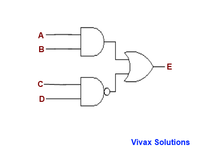
E.g.1
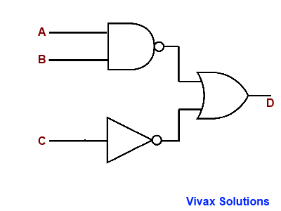
Since there are three inputs, the possibilities are, 23 = 8. Here is the animated answer.
E.g.2
Since there are four inputs, the possibilities are, 24 = 16. Here is the animated answer with some of the possibilities - not all.

E.g.3
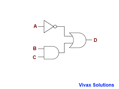
Since there are three inputs, the possibilities are, 23 = 8, in this case too. Here is the animated answer with all the possibilities.
Uses of Logic Gates
Logic gates are used in almost every electronic
device today that we take for granted; the following animation shows some of the role
played by them in the things that we use everyday.
Washing Machine
Have you noticed when the motor is turning on? the
right temperature, right water level and of course, the closure of the door -
for obvious reasons.
7-digit Decoder
This is how a calculator displays the digits.
Do you want to practise what you learn? Here is a book for you: